
Install
So I am going to reiterate a point here. Before you do anything on your vehicle. Make sure the steering-wheel and front wheels are dead straight. Then remove your key from the ignition-barrel. Then most importantly disconnect your negative terminal first from your battery and for extra precaution when dealing with SRS equipment disconnect your positive terminal. Make sure to do this in the correct order.
Okay let’s get this stupidly simple install done.
Removing the stock wheel
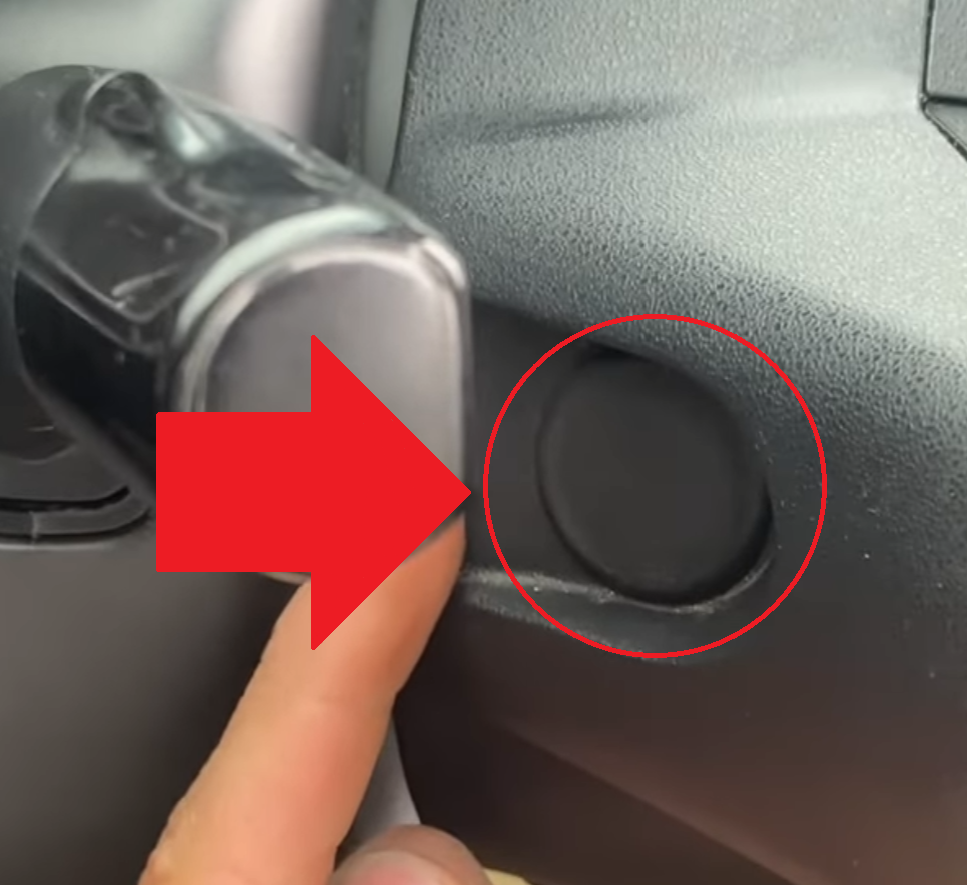
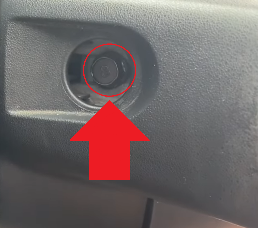
So in order to remove the stock steering-wheel with the precautions I mentioned above dealt with. You need to look at around the 4 o’clock and 8 o’clock position. There are two rubber bungs that you need to pull out and set aside somewhere safe to put back in the OEM steering-wheel after the jobs done.
Once removed you’ll see a 10mm head bolt in both these positions. Remove them and set aside somewhere safe for later.
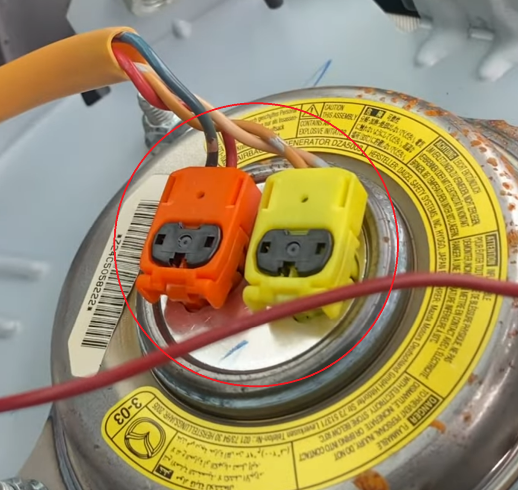
With these bolts removed the airbag is now free and should be handled with care and importance to the fact you are dealing with an explosive device. Carefully lift the airbag out and use a metal pick to pull the black plastic taps on the bag of the yellow SRS connector(s). Again, as mentioned way above in this article. You may have two yellow SRS connectors or just one. Anyhow, carefully store those black connector clips somewhere real safe. Then pull the yellow SRS connector(s) out from the airbag.
Set the airbag aside somewhere safe.
Now using an 1/2″ inch impact gun and a 17mm deep socket. Ensure your in reverse-direction and send it. Now before you completely remove the nut off the steering-column spline. Thread it back on a couple turns.
Now pulling the steering-wheel backwards with some might. I often found clouting it hard from the front of the vehicle backwards, working around the steering-wheel till it comes loose.
You can now remove the nut entirely. Then remove the steering-wheel.
Now to install your boss kit.
Unbox your boss.
Locate the dimple on the female spline section of the boss. That dimple needs to sit as close to the dimple on the steering-column spline. That way its a straight as you can get it. I will briefly stop and mention here that if the steering wheel is dead-straight and the front wheels aren’t sitting exactly straight (out by a small amount) then that can be fixed by adjusting the tie-rods on the front axle. All that needs to be done is taking the car to an alignment shop and have them shortern the tie-rod on the wheel that’s toeing out and lengthen the tie-rod on the wheel that is toe-in. This restores the steering back to dead-straight. It is normal for a boss kit even a Japanese made kit to sometimes be half-a-tooth off on the spline. It’s not mission critical if it’s out by a tiny amount.
Once you’ve noticed the dimple on the steering-coloumn and the dimple on the boss itself. Try your best to line up the splines exactly getting the dimples to line up as close as possible.
Now gently and even push the boss fully back to engage the splines. Once you beleive it’s back. Give it a firm couple taps around the circumference.
You can reuse the factory locking nut method (most are nylocks) or use the supplied new lock-nut method. I suggest use the OEM nut.
Now here’s the bit you have to be very cautious of. You may be able to find the factory torque spec for the steering-wheel lock-nut. However what many do is use the same 1/2″ impact gun you used to remove the nut. Set the impact-gun to the right direction. Use the middle power setting and give the nut about three ugga duggas. I cannot stress how important it is you DO NOT overtighten the nut as the bosses are usually aluminum and your using a grade 8.8 nylock to tighten. If over tightened you could cause hair-line fractures in your boss and that boss then is totally ruined. Remember this nut is very important so the wheel doesn’t just pull back off the shaft. That said it is a nylock and even if re-used once or a couple times more will still have a good locking effect against vibration. So DO NOT overtighten it. I cannot stress that enough. If unsure I suggest use a torque-wrench and use the steering-security-lock to lock the wheel one direction. Then have someone hold the wheel firmly while you tighten. Just be careful not to destroy your steering-security-lock by wrenching on it without someone holding the wheel to help resist the torque from your torque-wrench.
Quick-release install
Once your boss is on and tightened. Plug in the white-plug with the single horn wire provided in your kit to the clock-spring. Fish that wiring through the boss appropriately along with the SRS connector(s).
At this stage it can differ depending on your setup. Whether you use a quick-release or mount the wheel permentely. I will cover adding a quick-release as many will do this. However you can use the information to mount the wheel permemntley.
Start by getting the base of your quick-release and two bolts from the quick-release kit. These will be hex-bolts not countersunk allen-bolts. Pick up the ground-ring and offer it over the back. Connect either of the wires from the back of the quick-release connection points and slide the female spade onto the ground-ring. Slightly bend the tab to allow the connector to remain inside the void in the middle of the boss. Connect the other spade connector from the clock-spring single wire to the other terminal male-spade. Use some electrical tape to ensure these do not short and cause any intermittent faults.
Now start the two bolts and snug them up. Install the rest hand tight. There’s no torque spec for these hex-bolts. Simply nip them up using very little leverage and a 10mm spanner. DO NOT over tighten these. These bolts screw into an aluminum female blind thread so DO NOT over tighten them as you will ruin the boss.
Once the base of the base of quick release is tightened up, the rest can be done on a clean work bench.
Installing the steering-wheel
Start by unboxing your steering wheel. Gather the countersunk allen-bolts from your quick-release kit. Quickly run to the car with the other half of the quick release. Try spin the steering-wheel half of the quick-release until it clicks and locks with a loud ding. Then offer the steering wheel onto the quick-release and get two countersunk-allen-bolts started to ensure the wheel is installed dead-straight and not upside down. (Check the front wheels are straight before offering the steering-wheel onto the quick-release). Finger tighten the bolts. Remove the steering-wheel from the car and bring back to the bench to finish up the installation.
Install the remaining counter-sunk-bolts finger tight. Then using the appropriate allen-key with very little leverage. In a star pattern go around and nip the bolts up. Do this then go around in a clockwise orientation to ensure none are loose and feel as tight as the rest. Again DO NOT overtighten these. They are steel bolts into an aluminum-thread. There’s absolutely no need.
With the steering-wheel now secured to the quick-release. We can complete our wiring for the horn button. Start by getting some 1.5mm2 wire. Crimp on a fully insulated heatshrink male 6.3mm spade. Cut the wire to about four inches long. Strip back about 2.5 inches of bare conductor. Now wrap the wire around the horn button outter metal wedge lock. Then come back to the start of the insulation and wrap that tight. That will be are ground path back to the chassis ground. Some horn buttons have two spades on the rear. You may not need to do this. But most of the time you will. Plug the newly crimped male spade into the female spade connector from inside the quick-release. Then connect the other female spade connector from inside the quick-release to the male spade on the rear of the horn button.
Now carefully and accurately tuck the wiring inside neatly so nothing shorts out and offer the horn button back into the centre of the steering-wheel. Line it up so the logo is upright and straight. Then firmly press back and using the palm of your wrists push the horn-button back until it sits flat down and there’s no visible gap from the horn button outter-ring and the steering-wheels flat surface.
Offer the wheel back onto the car and spin the wheel a little to lock the wheel to the car. Then test the horn button operates the horn. Job done.
To explain the wiring that may confuse some. We use the ring-adapter between the boss and the quick-release base (or steering-wheel) to generate a return path to chassis-ground. On the horn button we wrap the horn-button outter-wedge-lock in copper wire to transfer that ground connection through the copper wire back to the hub. As the anodizing finish is not conductive.
Leave a Reply