
Ready for installation
Now you’ve decided to commit and purchase your Haltech ECU and WB1 controller let’s get into how we’re gonna install this fancy new equipment into your pride and joy. First we’ll tackle preparing the firewall to pass through your RoadsterWireWorks patch-harness. After that we’ll talk about mounting your ECU behind the glovebox. Then finally connecting up any Haltech accessories. Ready to have a look at trying to get the vehicle up and running. Which I’ve done an article on that can be found here.
Drilling your bulkhead/firewall
So my car being a UKDM model is RHD. This means on this particular shell I have an area where a LHD clutch-master cylinder would of been stamped into the shell. I’m going to use the centre of this stamped section for my Haltech 52mm grommet hole. For the rest of the world who is LHD such as my American counterparts, fear not. Although your harness routing and length will differ from a RHD vehicle where the harness essentially goes straight backwards to towards the firewall, a LHD car will instead make an L shape route from the stock ECU location and down the passenger side of a LHD car. To visually show what I’m talking about here is a comparison below of RHD and LHD bulkhead/firewall positions to drill the 52mm grommet hole.
Once you’ve marked your firewall position depending on if you’re LHD or RHD, it’s time to centre-punch the grommet hole. Then drill a pilot to suite your 52mm hole-saw’s pilot drill-bit. You’re going to want to start with a 4mm drill bit that will locate itself in your centre-punch divot. Then progress to one that’s slightly smaller than your hole-saws pilot drill-bit. This ensures your 52mm hole will be centered and not walk off in one direction as your drilling.
It’s important to mention that there’s no factory wiring directly behind either LHD or RHD positions. However there is a lot of white recycled sound insulation that will eventually snag your hole-saw as you finally penetrate through the firewall. So be aware of your drill is ultimately going to try snatch, a good idea would be to set the clutch on your drill if possible.
Once you’ve gone through with your 52mm hole-saw. Don’t allow the hole-saw to go deep. There is wiring further in the dash around these areas so be mindful. Once you’ve drilled through. You can tear out any of the insulation that’s all tangled and messed up. Just rip and tear until it is done. After that you’ll want to use a mix of a deburring tool and a needle-file to deburr both sides of the 52mm hole. Until it is completely smooth and you cannot cut your finger on the edge. This is important to stop your grommet getting cut during vibration etc. You should hoover up the swarf now. Then use some brake-clean or isopropyl alcohol and just clean both sides of the hole. What I suggest then is using a touch-up primer pen like the one link here. Just ensure the bare metal around the 52mm hole is covered in primer to stop future rust issues. It doesn’t have to be super pretty, its never going to be seen as the grommet has a fat thick lip to cover it. Give the paint like ten minutes to touch dry first. The 52mm hole is now prepped ready.
Passing the harness through
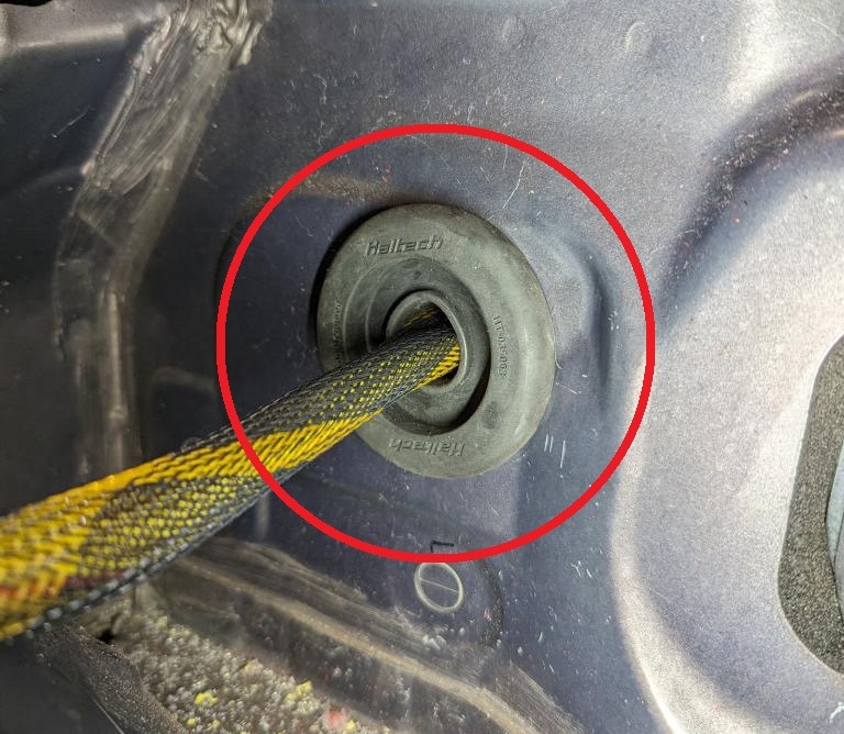
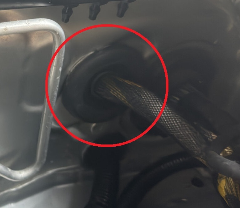
You’ll want to start very very carefully passing the two Haltech A & B Superseal ECU connectors through one at a time. You’ll have to stagger them a bit to do this. This is mission critical why the hole needs to be complexly deburred and filed smooth to avoid any wire damage on installation. DO NOT skip that step. Once you’ve got them through it helps to have a friend carefully reach for the harness as it lands in the interior. Making sure it does not get caught behind anything and is routed down passed the interior-fuse-box wiring. At this point once you have what appears to be a sensible amount of length in the glovebox/interior you can slide the already-on 52mm grommet down the harness and carefully install the grommet into the 52mm hole.
Okay so you now need to route the harness along the correct route to the stock ECU location. The route depends if you’re LHD or RHD. For RHD users you’ll want to route the harness along the factory fender wiring conduit. Along the inside of the conduit closer to the engine side. Run it along and peel down between the gap found between the strut-tower and the engine-bay-fuse-box. Then it can peel down into the area where the stock ECU is located. How you go about mounting the RoadsterWireWorks ECU-main-plug completely depends on your engine bay setup. You can either mount it flat like the stock ECU was. Or you can mount it upright like I did in my setup by making some custom brackets. Here are some examples below.
(slider of stock ECU lay flat location vs my upright version)
From here we just carefully zip-tie the harness in the engine bay giving some slack around the bends etc so nothing is taught. Do not sinch-up the zip-tie’s mega. Just snug them up around the main fender wiring harness and cut the excess of with some flush-cutters so they are not sharp. Nobody likes sharp zip-ties. In the interior hold fire until we mount the ECU until you decide to zip-tie.
For LHD users the engine bay routing is the same procedure but you’ll have to zip-tie the harness with the factory wiring that runs just under where the hood-latch is. Tucked up under neatly along the front of the car. Be mindful of contact with the hood-latch as you route the harness along there. Essentially you’re going to create an L-shape and route across the front of the car to the passenger-side of a LHD car and then follow the fender wiring conduit and stay on the inside closer to the engine side. To avoid the hood crushing the harness etc. Below I’ve done a quick sketch to show you the routing for both LHD and RHD variants of the kit.
(slideshow of LHD and RHD sketch of routing to firewall and ecu location)
Mounting the ECU behind the glovebox
So first thing’s first. Remove the factory glovebox by squeezing both sides in. Then remove the glovebox. We’re going to cut out the back section of the glovebox similar to the image below. This will allow us to still put our insurance documents, high-visibility-vest and a flash light etc in there. However it will clear the ECU.
(image of back of glovebox cut with red around the cut to exaggerate it)
Now with the glovebox modified by either a Dremel or tin-snips and the sharp edges cut down smooth with a Stanley-knife it’s time to mount the ECU. In order to do so we to create a simple bracket that will attach to the passenger side SRS airbag studs/nuts. I ended up using some 2mm thick aluminum for this and some stainless-steel riv-nuts to secure the ECU to the backing-bracket. My example is below. However I do no longer have the factory SRS equipment in my vehicle so you may find a better way to mount the ECU. Whatever you do, do not mount the ECU to glovebox because over time opening and closing the glovebox could potentially strain the wiring and cause an intermittent connection. You want the wiring harness stationary. I’ll let you come up with your own solution for this just use common-sense and you’ll be fine.
With the ECU now mounted via your bracket you can secure the wiring-harness under the glovebox around the bottom of the blower-motor area to the factory wiring that runs that way trying to avoid making removing the blower-motor difficult because of your harness is in the way.
Mounting your WB-1
Like the majority of this article, the location in the interior of the WB1 depends not only on your engine setup but if you’re LHD or RHD. What do I mean? Well in the instance of a turbocharged Haltech recommend your roughly a 1000mm or a metre away from the back of turbo exhaust flange. So that usually means the sensor will be closer to the transmission-tunnel and further back towards the AFT of the car. Meanwhile a supercharged or N/A setup means the sensor will sit further forward. Extending the fire-shielded O2 sensor cable is not an option. Instead the best and only way is to locate the WB-1 controller closer to provide sufficient length for the sensor cable to reach without strain and be able to be clipped away from hot or moving parts in the car.
For most turbocharged NC RHD setups I strongly suggest you mount the WB-1 controller in the same area the SRS-ECM is located. In my instance mine sits further back than that. Just under where the useless NC1 coin-holder is situated above the transmission-tunnel. This will work with and without the SRS-ECM remaining in the vehicle. However on a supercharged or N/A setup the fire-shielded sensor cable may not reach so you may need to think about placement in these instances. You might have to mount the controller under the steering-column like the factory modules that live under that area (to the side of the steering-column not directly underneath to clarify, like the factory flasher-module location).
For LHD users regardless of turbo, supercharged or N/A you can mount it behind the glovebox area with the ECU in unused space. But regardless of all of this. You will have to drill a 25mm grommet hole where you intend to penetrate out to the exterior of the vehicle. Then pass the O2 sensor fire-shielded cable through the grommet (de-pin it) and connect it to your WB-1 inside the vehicle.
Without getting far too technical for this article. I suggest you read the installation guide how to connect the WB-1 controller to your Haltech ECU. I will not cover this hear as it can depend, depending on what variant WB-1 you have. LSU4.9 (Bosch) or the better (NTK) sensor variant.
Ready to prepare to setup and configure
Okay by now you should have successfully completed the above steps and have the equipment installed correctly to suite your specific vehicle. If you have any other CAN devices you wish to connect from Haltech then I suggest you purchase their four-port DTM CAN hub that will give you three devices to connect instead of just one from the ECU’s four-pin DTM port. Not forgetting the WB-1 has a spare four-pin port. You can use this to connect another CAN device like a CAN keypad for instance. On my personal vehicle the CAN hub lives above the ECU on another bracket where the SRS airbag would of lived. Again you can be creative and mount it where you want within reason in the interior. With the CAN hub installed it is as simple as plug and play for other Haltech CAN devices. Such as a 52mm Haltech CAN gauge.
Thank you for reading this far and once you’re happy with your install, you can visit the next article in relation to this article about how to get your car up and running with little to no experience. Link can be found here for that. If you have done an install like this please share your thoughts and opinions on what you personally did in the comments on this article. Thank you once again.
Leave a Reply