Thumbnail Credits: Devin / Instagram: @nc1_devin
What are we going to do?
To briefly summaries, we will connect to the ECU via the laptop and upgrade the firmware so we can make use of the newer and better Haltech NSP (Nexus Software Programmer). Yes, Haltech kindly allow you to use the later Nexus series ECU’s programmer software on your older Elite series ECU. It’s awesome and can unlock more features too even with the slightly older hardware. Completely free of charge which is wicked.
Once we’ve upgraded the firmware to be able to use NSP on the laptop, we will download a base-map for our engine configuration. This is simply a base-map that allows us to start the engine and take the vehicle to a tuner. However before we even attempt to start the engine we’ve got ignition-timing to check and verify. Plus a whole host of other settings that we should enable prior to start to protect our engine. Because I’m a nice guy I will allow you to download my base-map file for free as part of this article. That will get you going. That said with any base-map you need to sit down for a couple of hours and go through every individual setting and remove or add wherever necessary. But don’t worry we’ll cover the basics here.
Understanding what we actually have
We need to be honest and humble with ourselves here. Do we actually know how our engine works mechanically and digitally? There’s no shame buying all this kit and still not having a full understanding how and why everything works together.
So even if you think or do positively know I encourage you to stick with me and maybe you might learn something you didn’t know? Okay cool. Our engine is going to be a four-stroke piston petrol engine. What does that mean? Let’s start simple, a four-stroke engine takes four cycles to complete a entire combustion event in the cylinder. Suck, squeeze, bang and blow. Put into proper terminology we have the intake cycle where air and fuel is sucked into the cylinder. Then we go into the compression cycle as we compress that air and fuel then at roughly TDC (Top-Dead-Centre; where the piston comes to the very top of the cylinder on the compression stroke). From there we get the power stroke or cycle. The highly compressed air and fuel mixture is ignited by the engines ignition system. Lastly the exhaust cycle where that spent air and fuel mixture is turned into different gases and is pumped out into the exhaust.
Cool so we understand a basic four-stroke engine and how it operates mechanically. That’s our first building block. Now a modern four-stroke piston petrol engine will not fire its ignition-system (the spark plug) at 0degrees or TDC. It will be advanced, what does that mean? So anything before 0degrees or TDC is considered advanced because you’re firing the spark-plug before cylinder one gets to the end of the compression stroke/start of the power-stroke. The opposite of this is called retarded. Because retarding the timing means firing the spark-plug after 0degrees or TDC. Now hopefully you understanding the meaning of retarding or advancing the timing.
In order to keep this article crystal clear I will not mention Variable-Valve-Timing or Variable-Valve-Lift and how they work and why they work. The image I’m building in your head is a very basic 2.0 litre DOHC (Double Over Head Cam) petrol engine. So forget about these completely for the purpose of learning.
Okay now let’s combine the knowledge we may have just learned. We know that the spark-plug must fire at the right time in order for the engine to make efficient power and not cause any engine damage. So this is the kicker. The ECU has to know where the four-stroke piston petrol engine is at in it’s cycles. This is critical for engine running. The ECU will use a crank-trigger sensor usually off of the front crank-pulley using a trigger wheel on the pulley with teeth and a missing tooth or teeth to verify. Essentially the missing tooth or teeth are a basic checksum if you like. A checksum for those unfamiliar with the term is a simple as it sounds. An equation happens and if everything is working properly that equation should have only one pre-determined answer. Such as 2 + 2 = 4. If 2 + 2 = 3, then that’s a failed checksum. It’s a simple logic check. Your ECU will actually do this self test every time it’s powered on.
The ECU will also use camshaft position sensors in conjunction of the main crank-position sensor. So your probably thinking so what? Well we need to verify when the engine is at TDC or 0degrees on the end of the compression stroke on cylinder one that our ECU is reading the crankshaft is at 0degrees or TDC. Not say 10 degrees advanced or retarded. Otherwise when the ECU runs the engine under normal ignition circumstances (not locked-ignition-timing) if the ECU wants to advance the timing to say 15 degrees the operational engine is actually firing the cylinder one spark plug at TDC at that exact value. This is vital we verify mechanical and ignition timing. As our fuel injection is also based off this math. So if we skip verifying the synchronization of the engine and the ECU we could cause catastrophic engine damage worst case scenario. Best case scenario if the timing is a little bit out we could be loosing potential horsepower.
I will quickly add that when dealing with most four-stroke piston petrol engines that ignition-timing is based solely off cylinder one. The degrees to clarify are relative to the crankshaft. A crank pulley is round, so that’s 360 degrees. However if we think about our four-strokes or cycles. To complete one combustion event the engine needs the crankshaft to rotate 720 degrees. Which is 360 degrees x 2 = 720 degrees. Basic math.
Connecting to the ECU
Now the base-map file you will receive should be very close to your specific engine. However we will check this anyway. So now your aware of the mission let’s get started. Start by powering your laptop on, download and install the software programmer. (If you have a newer elite model with the USB port missing under the waterproof cover then it will already have firmware capable of running the NSP software. If not you download the very last ESP software and run the upgrade process. In order to upgrade a ECU the process is documented here. So we’ve got the latest NSP release software on hand. Connect your USB cable to your ECU if you haven’t already done so. With the software already open you should see a dialogue box pop up. Click connect.
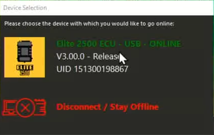
Once you have turned the ignition on and connected your cable you will have a dialogue box pop like this one. Click the ECU model to go online and communicate with the ECU.
Disabling fuel injectors
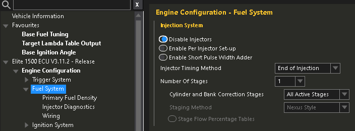
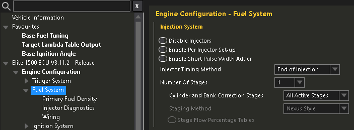
Once connected we will begin by disabling the fuel-injection. To avoid the engine firing when we check our timing synchronization. To do so we navigate to Engine Configuration > Fuel System (click the “Fuel System” text). Then he first setting Disable injectors, tick that. Now you can get into the habit of sending changes to the ECU. You will see a flashing power button to the right of the ECU connect button. Click that and this will save the changes and reboot the ECU. Remember to do this after every change if the reboot button is flashing. Not all changes will require a reboot but a lot will.
Setting up engine-protection
Next we will immediately make use of that three stage engine protection feature. To do this we navigate to Engine Functions > Engine Protection (click “Engine Protection” text). Let me give you an explanation and give you a recommendation about what behavior you may want setup. So you may or may not be aware with the Elite 1500 model you have three different engine protection modes to suite different problems as they may occur.
To get your head in the game I’ll give some examples of how you may want this setup depending on your preferences and vehicle purpose. So a basic street-car you will highly likely want the engine to completely shutdown if oil pressure drops below a pre-defined minimum value lets just say 15psi for this example. Makes sense right? Save the engine and shut if off faster than any human can. Potentially saving you a lot of money and work.
However on the contrast if the engine coolant temperature begins to overheat and oil pressure is still good. You may wish to richen the Air:Fuel ratio as in a four-stroke-piston-petrol engine the more fuel will help cool the cylinders and engine block down. However you make less power, but in this case it might make sense to do this for engine coolant temperature that has exceeded a certain value. Say 100 degrees Celsius. While the maximum coolant temperature may be able to exceed that value for short periods of time we wish to prevent the temperature sky rocketing any further.
So now to have something in the middle between increasing the fueling for an engine that’s getting hot and completely shutting off the engine. Let’s say its something has gone wrong and the engine coolant temperature has now started to exceed the 100 degrees Celsius that I previously mentioned. We need to take further action but let’s say the cars in an endurance race right. We want to keep moving to get to the finish line on our final lap. We might want to impose a lower rev-limiter as well as the richer Air:Fuel ratio to reduce the thermal energy inside the engine and thus cool it down. Especially since the water-pump is mechanically driven via the serpentine-belt off the crank. Unlike an electric pump we need to keep it going and to do that we need to keep the engine running. See the logic here? So we can set a rev-limiter at 3500rpm so that our driver can finish the race.
These are my three examples.
There are many many ways you can use existing Mazda sensors or additional sensors you’ve added to keep the engine from blowing itself to bits. Just to name a few below for inspiration and reference.
Sensor list
- Engine Coolant Temperature (Mazda)
- Engine Coolant Pressure (Not on the engine from factory)
- Engine Oil Pressure (Not on the engine from factory)
- Engine Oil Temperature (Not on the engine from factory)
- Wideband WB1 (your newly installed Wideband kit with the ECU)
- Fuel Pressure (Not on the engine from factory)
- Fuel Temperature (Not on the engine from factory)
- Intake Air Temperature (Mazda)
- Manifold Absolute Pressure (Mazda)
Stage one engine protection
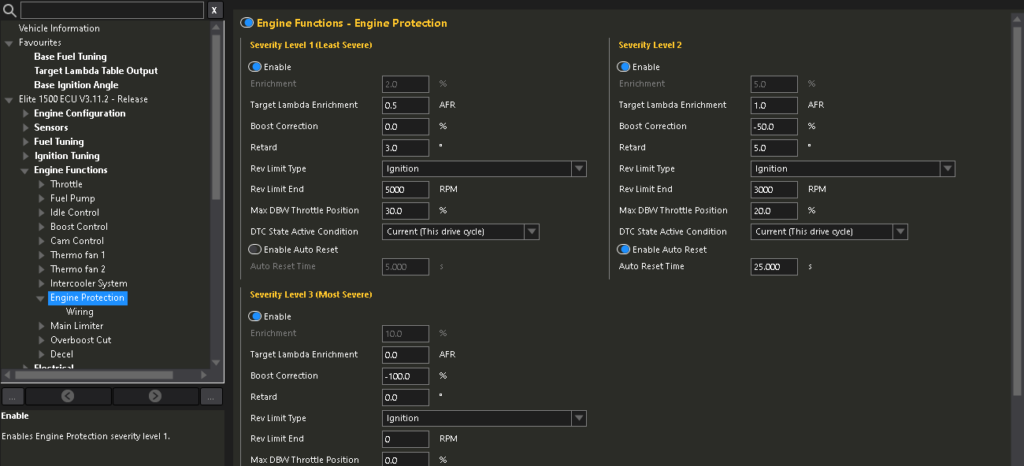
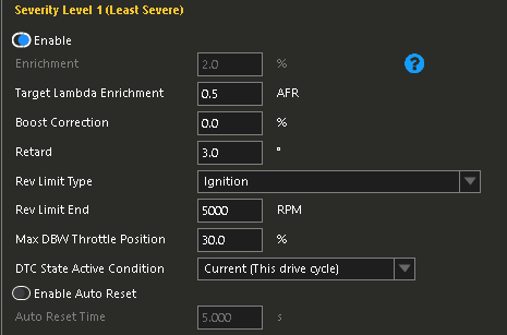
Okay so how do you put into practice what you’ve just learnt? So below I have attached an image of settings I’d suggest you use. But I will briefly speak about them. So stage one (least severe) Target Lambda Enrichment is at 0.5 AFR. I’ve retarded the timing by 3.0 degrees. In terms of four-stroke-piston-petrol engines speaking loosely retarding timing will make less power and less thermal energy. Useful for this purpose. The Rev Limit Type is set to Ignition. Unless you know what you are doing DO NOT set this to Fuel. You want the rev limiter done by killing ignition and governing the engine maximum speed. Using Fuel can cause all sorts of issues unless you know what you are doing. I have set the Rev Limit End to 5000rpm for stage one protection. I have then se the Max DBW (Drive By Wire) Throttle Position to 30%. My personal reasoning is without having to look down at any instrumentation I will know there’s an issue as my throttle response will be severely reduced. Lastly I have set the DTC State Active Condition to current. This means once the vehicle is shutdown, key out and then key reinserted the CEL (Check Engine Light) will have gone.
Again you do not have to copy these exactly by all means feel free to watch Haltech’s own video in the player below and fine tune these for your engine and vehicles purpose.
Stage two engine protection
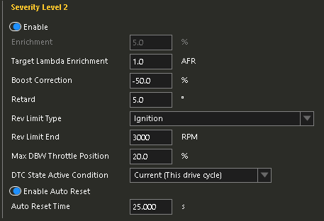
Moving onto stage two. I’ve increased the Target Lambda Enrichment from 0.5 to 1.0. Boost Correction is set to -50%. This setting cuts that percentage of target boost by the amount entered. So my logic is now something is getting worse so we must take more serious action to avoid having to shut the engine down which hypothetically could cook the engine due to what I previously mentioned about coolant circulation being stopped when the engine is not running. Not an ideal situation we try to avoid by this stage. Retard is set to 5.0 degrees so an increase by 2.0 degrees from Stage One. Rev Limiter End is now reduced further to 3000rpm. Again to reduce thermal energy in the engine. Max DBW Throttle Position is limited to 20% so the engine cannot be worked as hard. On this stage I have ticked the box that says Enable Auto Reset and my reset time is 25.000s. Which is represented in mila-seconds. So what this does is keep checking if the current state of the engine has changed then it will revert back. If not Stage Two continues activated.
Stage three engine protection (most severe)
This is the “OH SH!T” setting that will stall the engine to prevent potentially further damage. Target Lambda Enrichment is set to 0AFR as this does not matter anymore. Boost Correction is set to -100% removing all boost pressure. Retard is set to 0degrees as it does not matter, where are about to stop the engine with this setting so that no longer helps us. Rev Limit End is set to 0rpm so the engine will stall out. Max DBW Throttle Position is set to 0%. Disabling the throttle. DTC State Active Condition is set to Current and past. This means the CEL will stay illuminated even after cycling the key in the ignition.
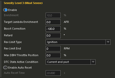
Remember to save all these changes and reboot the ECU.
Enabling wideband corrections
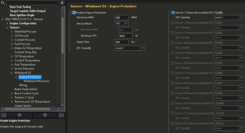
We can start enabling the oxygen sensor in the exhaust stream now. Go to Sensors > Wideband O2 > Engine Protection. Start by enabling Engine Protection. Set the Minimum RPM as 500. Precondition set to TPS. Minimum TPS 40%. Delay Time 650ms. DTC severity Level 2. This configuration means once a issue occurs with the wideband oxygen sensor it will trigger Level/Stage 2 engine protection that we setup earlier.
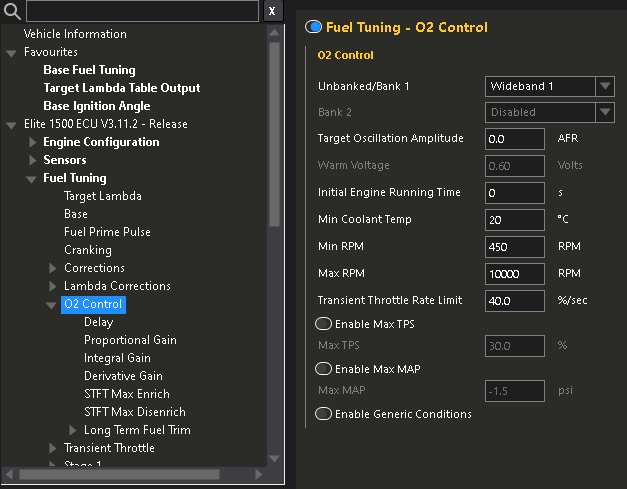
Head over to Fuel Tuning > O2 Control (click “O2 Control” text). Here you need select your WB1 wideband controller. To do this select the drop down box and find “Wideband 1”. Initial Engine Running Time is set to 0. That way it works straight away. Providing our Min Coolant Temp set at 20 degrees Celsius condition is met. Min RPM is set at 450rpm to avoid anything trying to interfere with starting the engine and allowing it to reach it’s target idle rpm. Max RPM should be set higher than the rev-limiter on your engine. That way it works from idle to max RPM. Transient Throttle Rate Limit is set at 40.0% a second.
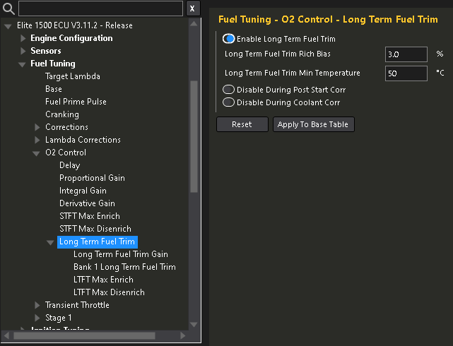
From here lets go to Fuel Tuning > O2 Control > Long Term Fuel Trim (click “Long Term Fuel Trim” text). Enable Long Term Fuel Trim. Leave the default values for the time being.
Entering in fuel injector data
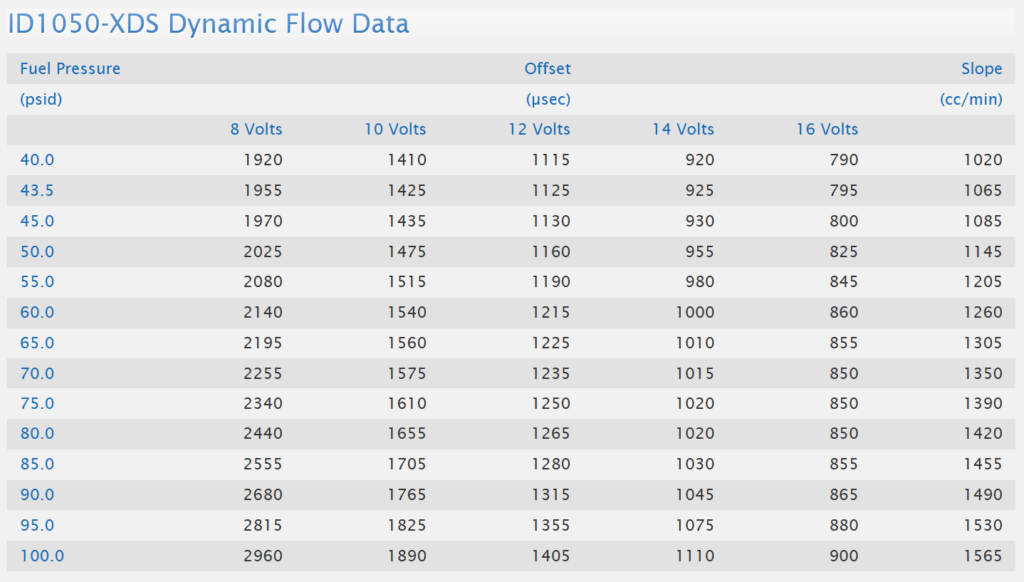
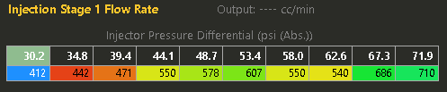
Now we need to tell the Haltech what specific fuel injectors we are actually using in order to calculate the math for fueling with them in mind. You may have stock injectors in your 2.0 or 2.5 or maybe yellow RX-8 ones. Or like myself you may have much larger fuel injectors. Whatever the case you need to accurately identify what you have. I will provide the 2.0 OEM injector and 2.5 injector information below. So feel free to copy it if that applies to you. If not and you have custom injectors like myself you will need to find a technical datasheet for your injectors from the manufacturer. Here’s an example datasheet showing flow rate below.
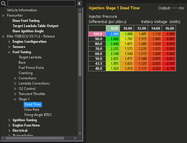
Injector Dead-Time
Injector Dead-Time is essentially how fast the injector responds at a different battery voltage. What actually is a fuel injector then? Simply a solenoid (a electronically actuated valve that once energized opens) and a very accurate fine mist nozzle. Injectors are just a two piece design. But the rate that injector will react when triggered is mission critical information for a stable tune. Injector manufactures take a lot of time recording this data for maximum efficiency. It is important you have provided the ECU accurate data here.

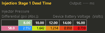
I strongly suggest you wire a Bosch Fuel Pressure & Temperature sensor like the one you can buy from Haltech here. This sensor will give you the ability to make use of more fuel injector data. You can see above the single line “Injector Stage 1 Dead Time” table. Notice to the left on the X axis there’s a single value in that cell? That “58.0” is the average pressure that the factory NC in-tank fuel pressure regulator outputs in PSI. Being a fixed-rate regulator that is the assumed pressure. However as you can probably imagine Base Fuel Pressure is not completely stable. So this will fluctuate. So it could vary between 55psi to 60psi. Problem is without a fuel pressure sensor the ECU cannot know exactly what the Base Fuel Pressure is at any given time. It’s going to assume it stays static. Which is not true.
That’s where I wish to make a suggestion to you. Wire in a sensor like the one I suggested from the common-rail back to the ECU. If I/O is unavailable then a Haltech I/O Expander device will serve to fix that dilemma. Anyways going back to the “Injection Stage 1 Dead Time” table if you click just above the table you will have the table editor open on your screen. Using the table editor configure your table to look like mine on the X and Y axis. Now re-enter your Injector Dead-Time data. You will have more cells to populate to make the ECU even more accurate. Wicked.
Injector Flow Rate
Let’s now tell the ECU the flow rate of our injectors. Now if we think logically. As the Base Fuel Pressure increases or decreases the amount of fuel that will flow through the injector will vary. So we use the information provided to us by the manufacturer to give the ECU more accuracy. Let’s head to Fuel Tuning > Stage 1 > Flow Rate. We can open the table editor again by left clicking above the table. Then add more PSI values on the X axis. You may have to use the PSI increments that your injector manufacturer provides. For example my manufacturer InjectorDynamics go up in 10psi increments starting at 20psi (ignore 43.5psi for a minute I’ll explain that later). But you may be working with injectors that are in .Bar, so will be like 23.2psi, 31.6psi and so on. Always adjust your scale values on your axis to whatever the manufacturer provides.
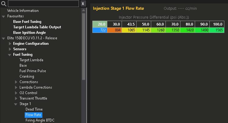
Quickly explaining that most manufactures will not use 40psi but 43.5psi values because 43.5psi is the generic aftermarket fuel-pressure-regulator value. That means 43.5 is your Base Fuel Pressure. If you have a Rising-Rate-Regulator then for 10psi of BOOST the Base Fuel Pressure value increases by that exact amount. If you’re not boosted don’t worry. Just note any aftermarket fuel-pressure-regulator should be set at 43.5psi or 3.0bar by default unless you have a good reason to increase your base pressure. In a boosted application you want to start low so you can allow for say 30psi of BOOST. Which would bring your Maximum Fuel Pressure to 73.5psi.
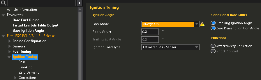
Locking ignition-timing
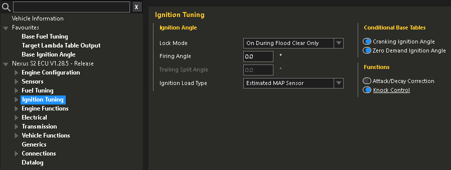
Before we attempt to try and crank the engine we need to lock the ignition-timing. Because we are going to verify 0degrees or TDC is showing as 0degrees in the ECU. So that the mechanical timing of the engine is synchronized with the ECU. So to do that we navigate to Ignition Tuning (click “Ignition Tuning” text). On this page we click the Lock Mode, drop-down box we change to Always On. Then Set the Firing Angle to 0 degrees.
Now we are in a position where we can technically crank the engine over and use our timing-light. However we need to create our 0degrees or TDC mark. Unfortunately a stock LF-VE or Duratech doe not have a timing mark on the crank pulley and the timing-cover. So we need to make one.
In order to create our timing mark. Disconnect both battery terminals so the car cannot crank. This is mission critical. You may have to remove more of the engine bay to get access to the crank pulley bolt. Once you can get to the lower front half of the engine in situ. You will need this SST (Special Service Tool) to screw into the side of the block to contact the cylinder one counterweight. You can purchase the SST kit for this engine here. To verify we are not 360degrees out of time we have to remove the rocker-cover. This is because we have a flat-bar SST that will only slot into the back of the camshafts if it’s at TDC.
Let’s start. Locate the blind-plug at the front lower left of the engine. Remove this plug and secure the bolt for later somewhere safe. Rotate the crank via a breaker-bar or large 1/2″ ratchet wrench on the crank-pulley-bolt. DO NOT rotate the crank counter-clockwise. Only rotate clockwise. Rotate the crank until the flats on the rear of the head line up with the flats on the intake and exhaust camshafts. The bar should fit in there tight. If it physically wont fit then rotate the crank again another 360 degrees. Try the bar again it should now fit. Now we can try and install the SST peg shown below into the front lower of the engine. It should screw in finger tight only. Then try and rotate the crank and you should feel it comes to a dead stop almost instantly as the cylinder one counterweight contacts the SST peg.
Now we have the SST flat-bar at the back of the head inserted into both intake and exhaust camshafts. The front lower timing SST peg in place and up against the cylinder one counterweight. We need to use a paint pen and create a mark that lines up on the crank-pulley and the timing-cover. Don’t make it too thick but ensure you use a steel ruler or so to create your marks so they are accurate. Congratulations you’ve just marked TDC on the engine for our timing-light.
Firstly remove the front lower timing-peg SST and replace it with the blind-plug you initially removed. DO NOT forget this step! Place the SST back in its packaging to verify it’s been removed. Then removed the flat-bar across the rear of the head out of the camshafts carefully. Reinstate the rocker-cover and rocker-cover bolts are all torqued to spec.
Finally we can use our spark-plug wire SST between cylinder one spark-plug and cylinder one coil-pack. Using our fresh timing-light we connect the 12VDC and GND clamps to a jump-pack or spare battery on the floor. Then connect our trigger clamp facing the correct orientation as the arrow shows facing the spark-plug direction over the new spark-plug cable portion of our SST.
Have a friend crank the engine on the key and watch the timing-light fire. Aim the light at your marks on the crank-pulley, the light should fire at the same time the timing mark on the crank-pulley is lined up with the front timing-cover. Just think the light represents cylinder one spark-plug firing. It should be firing at exactly TDC as that’s what we locked the Haltech ECU at on the ignition settings.
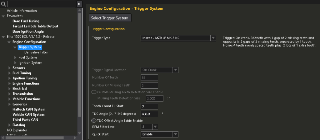
If your marks line up and your happy. Then good. If they are miles out that is a problem. Then you’d need to go to Engine Configuration > Trigger System (click the “Trigger System” text). Double check Trigger Type drop-down box is set to Mazda – MZR LF MX-5 NC. Then check the TDC Angle (0 – 719.9 degrees) is set at 400 degrees. If not there is your problem.
Now we can enable fuel injectors and start the engine. It will likely run like sh!t because we are firing ignition at 0degrees or TDC. To do this we navigate to Engine Configuration > Fuel System (click “Fuel System” text). Then untick Disable Injectors. Reboot the ECU to make the change.
Now start the engine, check timing again while its running. Then rev it a bit and make sure it doesn’t jump around as you rev the engine. If all looks good and your happy. Shut the car off. Remove the SST and put the cylinder one coil pack back to normal. Go into the NSP software again and head to Ignition Tuning (click “Ignition Tuning” text). Then change Lock Mode back to On During Flood Clear Only. Reboot the ECU and make the change.
Now restart the car and it should run healthier than before. You Sir or Madam have now installed the ECU, setup the very basics in the NSP software, verified ignition-timing is correct and finally started the engine for the first time on your new Haltech ECU. Job well done if you’ve made it this far.
Some notes, if you still have the battery in the front. What are you doing? For real though if you do still have the battery in the factory location you may need to use jump leads and lots of caution to temporarily relocate the battery to create and check your ignition-timing is set correctly. You should relocate the battery to the boot/trunk of the vehicle if you haven’t already.
Leave a Reply